Manufacturing in China Blog
Here you can leave comments and start discussions about manufacturing parts of complete products in China.
Heatsink Optimization – Thermal Design for maximum heat sink performance
- Hits: 5033
- 0 Comments
- Subscribe to updates
- Bookmark
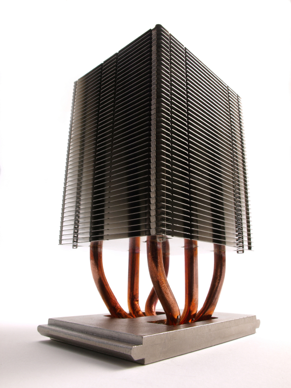 Optimizations for heat sink thermal performance often result in solutions that are not practical to implement either from a component availability or manufacturability point of view. This review describes the optimization process for a parallel fin heat sink with a dedicated fan for cooling. Some of the factors considered are fin thickness and density, fin height, overall lenght, and performance. The constraining factors are choice of fan and associated fan performance curve, weight, cost, and manufacturing technology. The technology places limitations on fin geometry. The emphasis is illustrating the complexity of the process and the number of factors to consider when pursuing an optimum heatsink solution.
Introduction
Heat sink optimization involves many different considerations: thermal, mechanical, fluid, and system environment all play a role, as does manufacturability. This paper explores these aspects of heat sink design in the context of a practical application, and shows the many limits on what is otherwise considered “optimization”. In reality, the design process incorporates many different limits in the search for a suitable thermal solution that is easy to manufacture and works in the target system.
Analysis
This design task is carried out using thermal and pressure drop performance calculations that include developing flow, fin efficiency, and heat spreading in the base of the heat sink. More specifiically, the pressure drop for any given velocity between the fins is calculated using fully-developed flow correlations [1] in rectangular channels, varying with aspect ratio. Heat transfer calculations use developing flow correlations between parallel plates [1], corrected for channel aspect ratio [3], for the heat transfer coefficient. Air temperature rise is taken into account using the same log-mean temperature difference method as for heat exchangers [1]. Fin efficiency calculations are included to obtain the total fin-side thermal resistance. To obtain the total thermal resistance, an additional spreading resistance [4] is added to the finside thermal resistance. This spreading resistance captures the competing effects of heat spreading and conduction through the thickness of the base and is well documented in [4]. The fan operating point will be at the intersection of the heat sink pressure drop characteristic [5]. Among the many assumptions are a few key parameters: that the fan curve is valid even when the fan is directly adjacent to a parallel array of fins. The technology of choice for this application is convoluted or folded fin attached to an extruded base. Although there are other inexpensive heat sink manufacturing technologies like CNC machined, most of them carry geometric 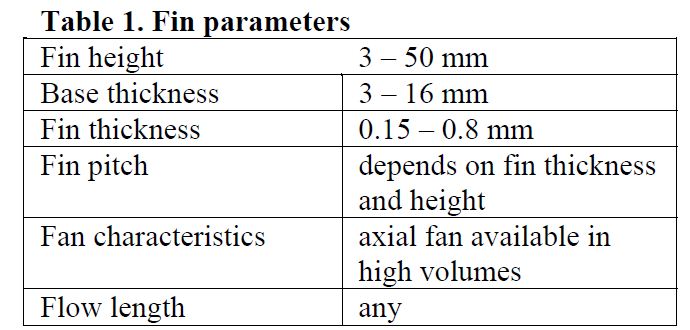 constraints that limit the minimum thickness of the fin. For example, a typical fin thickness in an extruded heat sink is 1.5 to 2 mm. This dimension along with the fin height limit of about 50 to 75 mm gives a thermally thick fin. It also limits the number of fins, in conjunction with the aspect ratio of the inter-fin space, that it is possible to fit on a given width of heat sink base. In a bonded-fin heat sink, the fin is typically 1.3 mm thick and must have a stable insertion. This insertion constrains the heat sink base to a minimum of about four times the fin thickness. For convoluted fin technology, the fins can be made in nearly any thickness up to 1 mm, and all the fins are made from a single piece of material. This strategy minimizes the number of parts in the heat sink assembly.
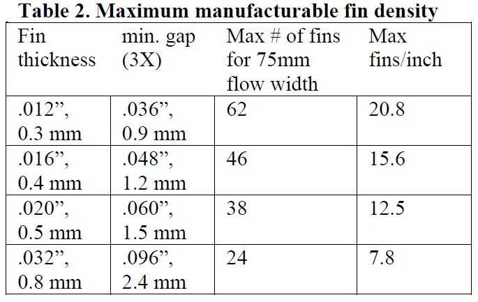
 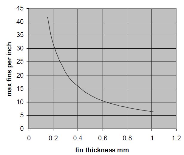 The overall physical envelope for this particular application, including the fan, is an 89 mm cube. The fan is mounted outside the fin pack such that the air flow direction is parallel to the fins and to the heat sink base. The flow is confined to the fin area by a cover plate on the top. Were the fin envelope to be smaller than the fan, the flow would be shrouded to the front face of the fins, rather than allowing some of the air to bypass the fins. The thermal load is 20mm x 20mm and dissipates 75 W. The table below shows the parameters to select to specify the heat sink design and the manufacturable limits of each parameter. The constraints on fin pitch are related to the fin folding machinery and come directly from the manufacturer of the apparatus. The fin spacing (gap) must be greater than a certain multiple of the fin material thickness. For fins up to 75 mm long and 25 to 50 mm high, the multiple was 3.0. This results in the constraints on maximum fins per inch illustrated in Table 2 and Figure 1.
The thermal performance target for the total solution was 0.27 C/W including the effect of heat source spreading, air heating, and fin performance. The flow rate resulting from the fan is obtained from the intersection of the heat sink pressure characteristic and the fan characteristic curve. While some deviations from the fan curve are inevitable in practical applications, the local optima are not expected to shift dramatically.
Number of fins and fin height variation
The effect of varying the number of fins in a constant 75 mm flow width is shown in Figure 2 below. The chart shows the fin-side thermal resistance. The effect of changing the fin height is shown in the different curves. For this comparison, we assumed 0.8 mm fins. Varying the number of fins implies that the fin spacing varies, so that the overall flow width is fixed. For each fin spacing, the heat transfer coefficient and pressure drop is re-calculated. The results are shown in Figure 2. Note that as the number of fins increases, the space between the fins decreases. Smaller inter-fin spacing increases the pressure drop for a given volume flow rate. Coupled with the fan curve (in this case a typical 60x25 mm fan), this impedance increase gives a decrease in the total volume flow rate supplied by the fan. At the high end of the range of number of fins, the volume flow rate through the small spaces is so low that air heating outweighs the heat transfer coefficient advantage of the smaller spacing, and dominates the thermal resistance. 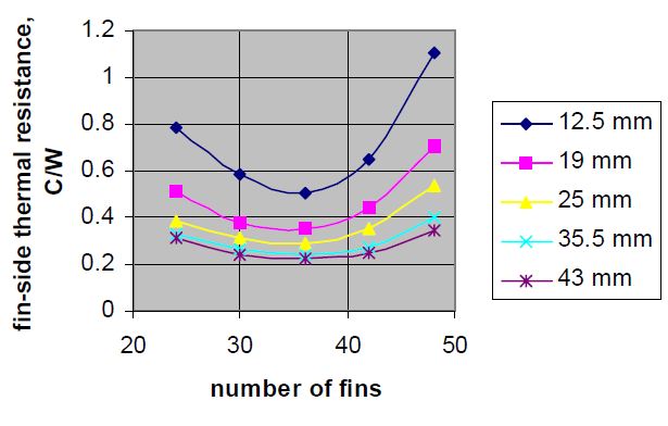 At the low end of the range of number of fins, there is simply not enough fin area to achieve high performance. These two competing effects produce the minimal in the curves shown in Figure 2. Performance factors aside, there are physical limitations to producing a viable heat sink. Comparing the performance curves in Figure 2 to the manufacturing limits in Figure 1 and Table 2 results in the conclusion that the only manufacturable combination for 25 mm or higher is the lowest number of fins (24). There are a few conclusions to note at this point. Most significant is that the sensitivity to number of fins decreases as the fin height increases. The larger flow space has lower pressure drop. Making the fin space narrower by adding more fins produces less increase in pressure drop for a tall fin space than for a short one. Keep in mind that the fan responds to higher pressure drop by deliving less volume flow rate. The lower flow rate translates to a higher air temperature rise contribution to the thermal resistance. Secondarily, the addition of fin height brings less and less performance return as the fin height increases. This effect stems from the decrease in air speed (and thus heat transfer coefficient) and from the decrease in fin efficiency. It is worth noting at this point that experience shows that the thermal resistance is typically not quite as sensitive to the number of short fins as the calculations indicate. However, low flow rates at high pressure drops should be avoided to minimize acoustic noise in the system.
Base thickness variation
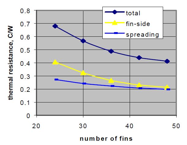
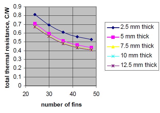
Figure 3 shows the relative contribution of fin-side and spreading resistance. The spreading resistance shows only a weak dependence on the number of fins, and is a significant contributor to the total thermal resistance. Thus, it is worth exploring the sensitivity of that resistance to base parameters. Figure 4 shows the effect of varying the base thickness for a constant total height of 50 mm with 0.3 mm thick fins and a 24 mm square source, again using a 60 mm fan. The total thermal resistance is the sum of the spreading resistance and the fin-side resistance. The spreading resistance in reality is probably somewhat less than calculated here because some spreading already occurs in the chip package. However, one may still conclude here that the spreading resistance is nearly independent of number of fins, since all the curves are parallel. It is also apparent that increasing the base thickness beyond 7.5 mm results in negligible performance improvement.
Fin thickness variation
The effect of varying the fin thickness is illustrated below for 43 mm tall fins and a 60x25 mm fan. It is interesting to note that the minimum fin-side thermal resistance can be obtained by more than one theoretical fin construction. However, because of manufacturing constraints such as diecasting, not all the possibilities shown in Figure 5 are realistic. The selection 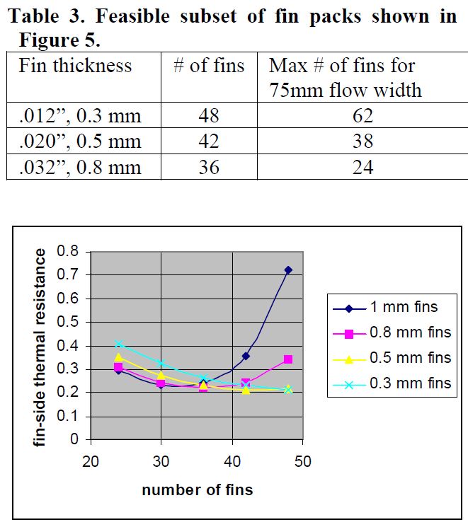 therefore tends toward a greater number of thinner fins, since with the thick fins maximum number of fins is not enough to optimize the thermal performance. Table 3 shows the feasible optimum combinations. This feasibility stems from the manufacturing limitations shown in Figure 1 and Table 2. Compare these combinations to Figure 5: many thin fins (48 at 0.3 mm thick) give better performance (approx. 0.22 C/W) than fewer, thicker fins (36 at 0.8 mm thick, approx. 0.25 C/W), given a specific air moving device. The parameters of the air mover govern the location of the minimum thermal resistance.
Fan characteristics
Many of the Figures above show sharp performance decreases as the fin array spacing decreases, most likely as a result of air heating (insufficient air volume). Figure 6 illustrates this phenomenon with 36 fins at 0.8 mm thick and 43 mm tall. Two performance curves are shown: one for the original 60 x 25 mm fan, and the other for a 60 x 15 mm fan. This suggests that a larger, more powerful fan could benefit the thermal performance. 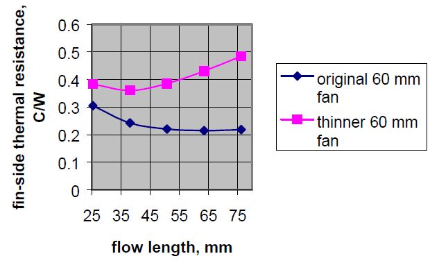 Flow length variation
Since the fin height, number and thickness now is constrained by manufacturability, it is worth checking whether the flow length has any effect. It is possible, as the upper curve in Figure 6 shows, that an increase in the flow length (and thus fin area) could paradoxically increase the thermal resistance. This performance degradation is caused by the higher pressure drop of the longer flow length and the flow delivery characteristic of the fan. 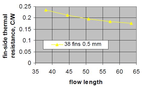
The graph below is for 50 mm tall fins and a larger, 80 mm fan. Since the fan mounts directly at the inlet face of the heat sink, the fan thickness must be included in the overall size envelope. A 75 mm envelope and a 25 mm thick fan leaves 50 mm flow length, which has been the standard up to now. It is evident that a slightly longer envelope may bring small improvements in thermal performance with a sufficiently powerful fan, but that even that strategy has its limitations. This limit can be seen in the flattening of the performance curve in Figure 7 as the flow length increases.
Conclusions
Practical design considerations often place significant limitations on heat sink “optimization”. Moreover, using a fan curve-based design method sometimes results in performance effects that run counter to conventional wisdom. However, these real phenomena cannot be ignored in the development of a suitable system thermal solution.
Comments